 Most people in the pump industry have not heard this term. To be perfectly honest with you, I’ve known about this issue, but only recently found the proper term. By definition, radial thrust occurs within a centrifugal pump operates too far from its Best Efficiency Point (BEP), resulting in imbalanced forces that push along the radius of the pump impeller. In plain English, the pump shakes and sounds like it is cavitating. Try to throttle the discharge valve of a pump while it is operating at full speed, and you will see what I am talking about.
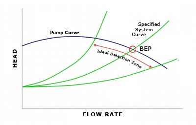
 Think about this another way: ever look at a pump curve and wonder why the BEP is located where it is? The Best Efficiency Point for a particular pump is plotted by the manufacturer onto published performance curves. The pump is most efficient at that operating point because it is the point that the forces within the pump are most balanced, resulting in the fewest losses. That certainly makes sense. It would stand to reason that as you move away from the BEP, the internal forces become less balanced. At 1800-RPM, you could imagine imbalanced pressures would have a profound affect on the life of the equipment. Ever wonder why pump manufacturers do not plot every line and every curve all the way from y-axis to x-axis? The conditions outside of the published operating curves are unstable and are NOT recommended for normal operation by the manufacturer.
Further evidence of this is found by looking at some manufacturer’s NPSHr lines plotted within their pump performance curves. Most of us know that as you increase flow (GPM), the Net Positive Suction Head required increases. More flow requires more pressure at the suction. As the flow decreases, NPSHr goes down. EXCEPT, at the left end of the NPSHr line, some are shown with a slight tick upwards, and none are plotted all the way to GPM = zero. This is because the forces inside the volute (wet end of the pump) are so imbalanced and so unstable, it would be impractical to plot. Plus, it would be unwise to plot conditions at non-recommended operating points.
Does this mean that NPSHr increases as you approach no-flow conditions outside of the published operating curve? Will we cavitate at these conditions? To a degree, I would say “yes”. Low-pressure pockets within the volute may cause cavitation, and it is audible. But this is not cavitation in the conventional sense. If you are operating outside of the published pump curve conditions, my response to the above questions is that you have bigger problems to worry about. Why is your pump operating under these conditions? Is there an obstruction in the piping? Is the piping layout imbalanced, promoting unstable operating conditions (especially in open systems like condenser water loops)? If we are operating to the right of the published curve, is the system not balanced or is there a piping leak?
Brief pump operation at shut-off conditions may be useful when troubleshooting pump and system issues, but sustained operation at or near these conditions will result in failures. In short order, bearings and seals will fail, followed by more catastrophic damage to the pump.
So, next time you wonder why a pump is cavitating when it has plenty of suction pressure, consider Radial Thrust as the issue, and then ask what system conditions might be causing these imbalances within the pump. It is not enough to treat the symptom – find and solve the real problem! For an onsite consultation from an experienced professional, contact your local manufacturer's representative.
Blog imags from 2012 ASHRAE Systems and Equipment Handbook, HVAC Systems and Equipment, Chapter 44, Centrifugal Pumps

.png)


Submit a Comment